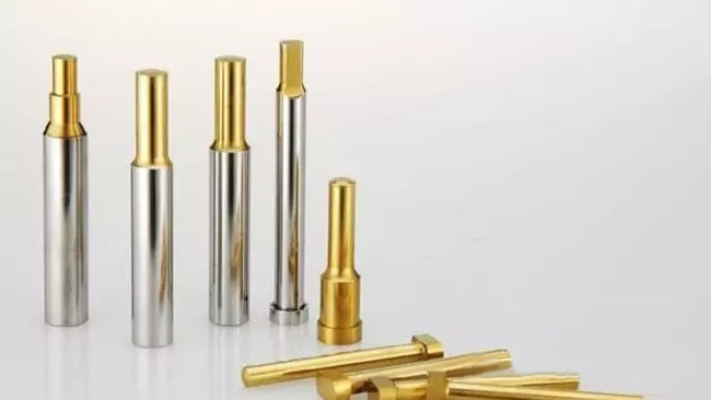
The punch is referred to as “formed cutting punch”, and the insert is referred to as “gate insert or inlet”, which is a very important existence in the structural design of the stamping punching tools. As long as there is a little problem here, it will directly affect the product quality.
Cutting Punches’ Design Principle and Punches structure theory
There are many forms of punches in the mold, and there are national standards for punch structures with circular cross-section. For the punch structure of non-circular section, it needs to be determined according to the shape of the product, the materials, cutting process.
1 The structure of the round punch
At present, the common circular punch structure forms in the mold are as follows:

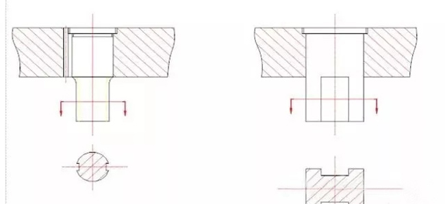
For round punches, it can be simply understood as “A” punches and “T” punches. The difference is that the punch is divided into first, second, and third steps. T punch is generally used in the case of relatively large punching, while A punch belongs to a modified version of T punch and is used in the smaller position of punching.
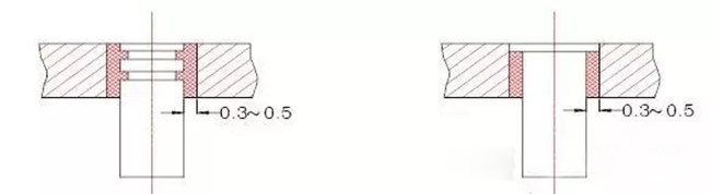
When the punching material thickness and hole diameter are similar to the small hole punch structure, in order to improve the longitudinal bending resistance, the shield sleeve structure form is adopted. As shown in the figure below:

If the parts are very large or there is space for blanking, the punch often adopts the structure form of the figure below to ensure strength and easy installation.

2 Non-circular punch structure
The non-circular punch needs to determine the shape according to the cutting process, but we can properly understand it as round and square. If the workpiece belongs to the circular category, the fixed part of the punch can be made cylindrical; If the workpiece belongs to the square class, the fixed part of the punch is also made square.
The following figure can be used to reduce the complexity of punch manufacturing, and non-cylindrical punches fixed with cylindrical shapes should pay attention to the positioning of the punch. Generally, riding sewing pins are used to prevent the rotation of the convex machine.
3 The Fixed Form of Punch
The most common method is to fix the punch with a splint, and a gap fit is used between the punch and the splint. The gap can be appropriately scaled according to the accuracy and thickness of the mold, and generally 0.01mm on one side.
The punch can be made into an assembly step shape (larger diameter). Generally, small and medium-sized punches are fixed in the form of rivet heads. Especially multi-head dies, in the case of a small distance between each other, the step structure will interfere with each other, and the riveting head structure is relatively compact.
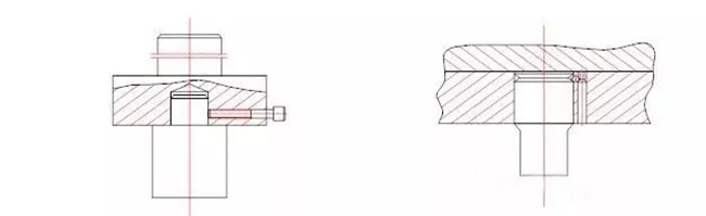
It is also possible to fix the punch directly with the upper mold base. This is generally used for blanking larger workpieces for fixation. Making a punch into an insert quick release is also a good option. Replaceable punch, mostly used for punches that are particularly prone to wear and some small punches in large stamping dies. Because these punches are easily damaged and need to be replaced frequently.
The operation and replacement of this structure can achieve quick replacement without disassembling the entire upper mold, which can better reduce the mold repair cycle. In addition, there is also the method of using glue filling, which is generally not used much now, so we will not go into detail here. The details are as follows:
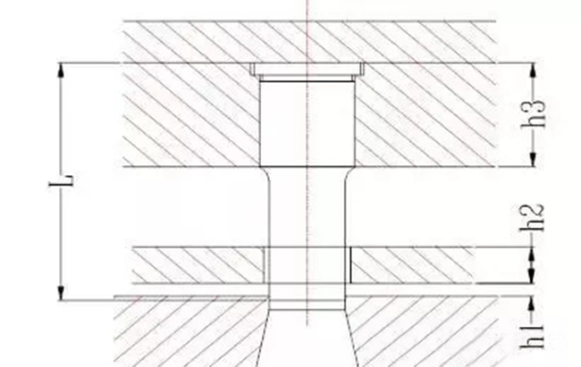
4 Determination of punch length
The length of the punch is generally determined according to the structure of the stamping mold. And theoretically it is determined by looking at the thickness of the upper mold template. In general, the shorter the lower the better before meeting the structural and use requirements. The length of the punch can be calculated as follows
L=h1+h2+h3+(10~20)(mm)
h1——Guide ruler thickness(mm)
h2——Pad thickness(mm)
h3——Punch fixed plate thickness(mm)
The 10~20mm in the formula includes the depth of the punch into the inlet, the grinding amount of the punch, and the distance between the discharge plate and the punch splint in the closed state of the stamping mold. The length of the punch should be modified according to the different structure and requirements of the stamping mold during design.
Under normal circumstances, the strength and hardness of the punch do not need to be calculated, only when the section of the punch is very small and the material to be punched is very thick and hard, it is necessary to check the strength and hardness of the punch.
Generally, Punch structure design is very important in the stamping mold, and precision carbide punches making with high precision is also very important.